Killing Chatter: How Endmill Geometry Fights Vibration
▶ VIDEO: Watch Before You Read
The video above walks through each geometry feature with animation. This article goes deeper on the physics and gives you a practical framework for tool selection. The two work together — use both.
If you run a CNC machine long enough, you know the sound immediately. That harsh, high-pitched screech cutting through the shop floor noise. Chatter. And the moment you hear it, you know something is wrong… With your surface finish, your tool life, and possibly your part.
The instinct is to back off the feed rate, slow the spindle, or reach for coolant. Sometimes that helps. Often it doesn’t. That’s because chatter isn’t fundamentally a speeds-and-feeds problem. In most milling applications, it’s a geometry problem… And the solution was engineered into the end mill before it ever touched your workpiece.
This article explains why chatter happens at the tool geometry level, and breaks down the three design features; variable pitch, variable helix, and progressive helix, used by modern high-performance end mills use to suppress it.
What Is Chatter, Exactly?
Chatter is self-generated vibration in the cutting system. When an end mill engages a workpiece, the cutting forces cause the tool, spindle, and workpiece to deflect slightly. If the frequency of those deflections aligns with a natural resonant frequency of the system, the vibration is amplified rather than damped. Each cut excites the next. The oscillation builds, and you get chatter.
The consequences are well understood in any machine shop:
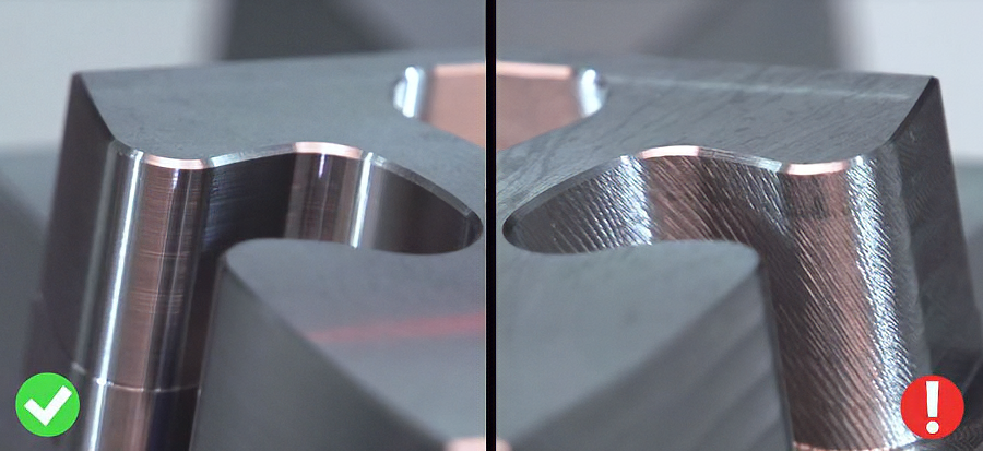
- Degraded surface finish — chatter marks left in the part
- Accelerated and unpredictable tool wear
- Increased risk of tool breakage, especially in small-diameter or long-reach applications
- Spindle and fixture loading that shortens machine life
- Scrapped parts and lost production time
The conventional response is to reduce depth of cut, reduce feed rate, change spindle speed, i.e., address the symptom by changing the energy input to the system. That works, sometimes. But it usually means running slower than is otherwise desirable, leaving productivity on the table.
The more effective long-term approach is to select tooling that is geometrically designed to prevent the resonance condition from occurring in the first place.
Why Standard End Mills Are Prone to Chatter
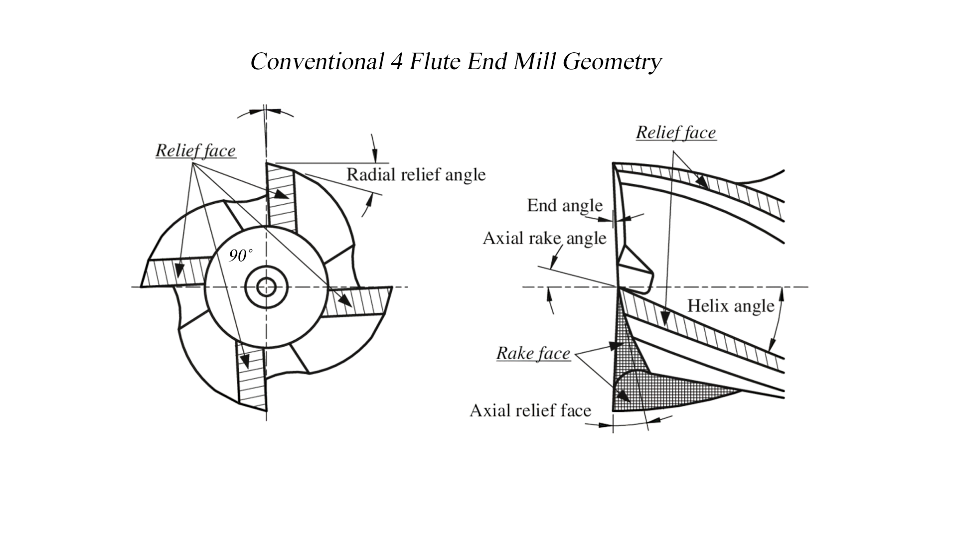
A conventional 4-flute endmill has flutes spaced at perfectly equal intervals — 90 degrees apart. It’s the obvious geometry: symmetrical, balanced, and straightforward to manufacture.
The problem is that equal spacing means equal timing. Every flute impacts the workpiece at the exact same interval during rotation. That regularity creates a single, consistent cutting frequency. When that frequency aligns with a resonant frequency of the system which depends on tool extension, workpiece material, fixturing, and machine characteristics, the impacts reinforce each other rather than canceling them out.
–> The Swing Analogy
Think of pushing a child on a swing. If you push at precisely the right interval, every cycle, the amplitude grows larger and larger with each push. You’re not adding more force, you’re timing it perfectly. Chatter works the same way: regular, predictable impact timing allows the vibration to build with each successive cut. Disrupting that timing collapses the resonance.
A symmetrical endmill isn’t a bad tool. For many applications — lighter cuts, highly rigid setups, softer materials — it performs fine. But in conditions where chatter is a real risk, the geometry itself is working against you. That’s where variable geometry end mills come in.
The Three Geometry Features That Suppress Chatter
1. Variable Pitch
Variable pitch is the most direct response to the equal-timing problem. Instead of spacing flutes at equal angular intervals, a variable pitch end mill offsets the flutes slightly from each other.
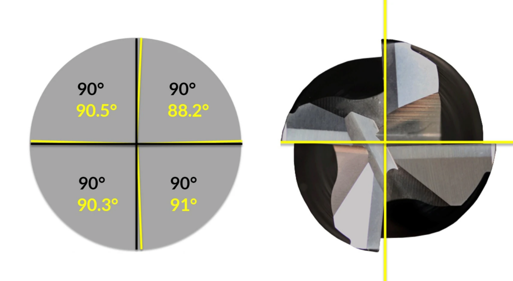
On a 4-flute variable pitch tool, the spacing might look like 90.5° / 88.2° / 90.3° / 91°, or some other asymmetric distribution, rather than four identical 90° segments. The flutes still all engage the workpiece during each rotation, but they don’t all arrive at the same time relative to each other.
The effect on the cutting system is significant. Instead of a single dominant impact frequency, the tool generates multiple frequencies staggered across the rotation cycle. These frequencies don’t combine constructively — they partially cancel. The resonance condition that allows chatter to build is disrupted before it can establish itself.
The key insight: you don’t need to eliminate cutting forces to eliminate chatter. You just need to prevent those forces from arriving at a consistent, reinforcing cadence. Variable pitch achieves this at the simplest level… Flute spacing.
2. Variable Helix
Helix angle is the angle at which a flute spirals up the shank of the endmill. A 38° helix means the flute makes a 38° angle relative to the tool axis as it winds from tip to shank.
On a standard end mill, every flute has the same helix angle. On a variable helix end mill, each flute has a different angle. For example, 38°, 37°, 39°, and 35° on a 4-flute tool.
The practical effect is that each flute engages the workpiece at a slightly different rate along its axial length. Where one flute is fully engaged, another is partially engaged at a different rate. The axial cutting force distribution is constantly shifting. The tool never settles into a repeating pattern that can lock into a resonant frequency.

Variable helix works on a fundamentally different axis than variable pitch. Variable pitch disrupts chatter at the spacing level… When flutes arrive. Variable helix disrupts it at the engagement level — how each flute engages along its length. Used together, they address chatter through two independent mechanisms.
2. Progressive Helix
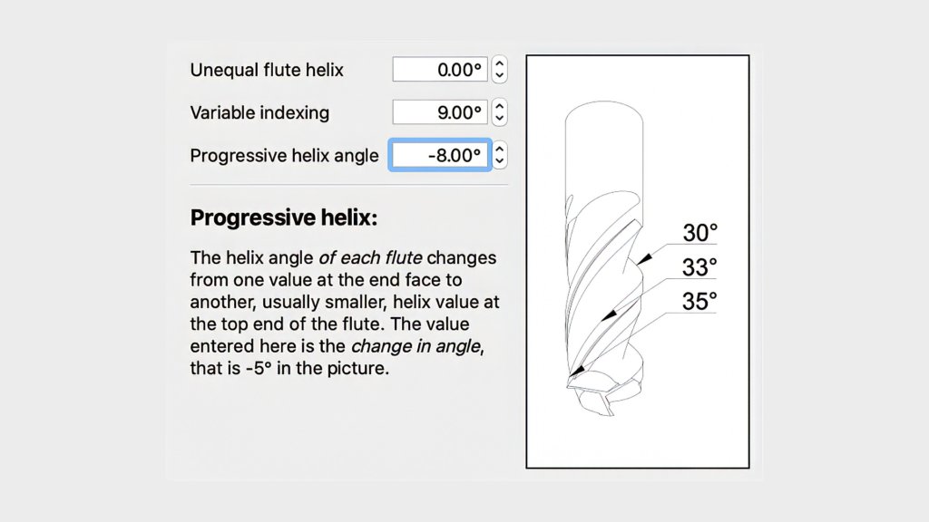
Progressive helix takes the variable helix concept one step further. Rather than assigning a different fixed angle to each flute, progressive helix changes the helix angle along the length of each individual flute.
A typical implementation might transition from 40° or 42° at the cutting tip down to 37° or 38° near the shank. The helix angle is continuously variable rather than constant.
The result is a cutting engagement that is never uniform along the depth of cut. At any given instant, different portions of the flute are cutting at different effective helix angles. The force vectors are constantly changing in direction and magnitude. There is no stable resonance condition to lock onto.
Combined Features in Practice
Many high-performance end mills incorporate all three of these features simultaneously: variable pitch, variable helix, and progressive helix. This is not redundancy. Each feature attacks chatter through a different physical mechanism: spacing, per-flute engagement rate, and intra-flute engagement variation. The combined effect is dramatically more stable cutting behavior than any single feature alone, particularly in long-reach applications, thin-wall features, and difficult materials.
Practical Tool Selection Guide
Understanding the geometry is useful. Knowing when to specify it is what matters on the shop floor. Here’s a practical framework:
When Variable Geometry Is Worth the Premium
- Long-reach or high-aspect-ratio cuts where tool deflection is unavoidable
- Thin-wall features that lack the mass and rigidity to damp vibration
- Hard or difficult materials (hardened steel, stainless, Inconel, titanium) with high cutting forces
- Setups with any flexibility in the fixturing, workholding, or part geometry
- Applications where surface finish is critical and chatter marks are unacceptable
- Repeat jobs where chatter has been a persistent problem with standard tooling
When Standard Geometry May Be Sufficient
- Short, rigid setups with excellent workholding and minimal stickout
- Softer, free-machining materials with predictable cutting forces
- Roughing passes where surface finish is not critical and you’re not operating near resonance
- High-volume production applications where the operating parameters are well-dialed and stable
If you’re not sure which category your application falls into, the decision is usually simple: if chatter has been an issue, or if the setup has any of the risk factors above, the premium for variable geometry tooling is almost always recovered quickly in reduced cycle times, better surface finish, and lower tool consumption.
A Note on Speeds, Feeds, and Geometry
Variable geometry end mills are not a substitute for proper speeds and feeds. They suppress resonance, they don’t compensate for running a tool outside its recommended parameters.
In fact, one of the advantages of chatter-resistant geometry is that it allows you to run more aggressively within the correct operating range. The tool’s self-dampening behavior means you can often push depth of cut and feed rate closer to the tool’s rated limits without inducing vibration. That’s where the productivity gains come from.
If chatter persists with a variable geometry tool and correct parameters, the issue is likely in the setup… Workholding, end mill extension, toolholder runout, or machine condition — rather than the tool geometry itself.
Find the Right Tool at Chapman
W.C. Chapman & Sons stocks high-performance endmills from Helical Solutions, Harvey Tool, Garr Tool, Mitsubishi Materials, and more… Including tools that combine variable pitch, variable helix, and progressive helix geometry for the most demanding milling applications.
Our team has the application experience to help you match the right geometry and coating to your specific workpiece material, setup, and operation. If you’ve been fighting chatter and want a second opinion on tooling, we’re a phone call away.
🛒 Shop Endmills
📞 Talk to Our Team